Industrial Designer  ·  Philadelphia, PA  ·  2026

Designyou canhold.

Architect turned industrial designer. Three years, 20+ projects — from furniture to inclusive tech to everyday objects.

Furniture Design ·Inclusive Design ·Ergonomics ·3D Printing ·Prototyping ·DFM ·SolidWorks ·Rhino 3D ·User Research ·Furniture Design ·Inclusive Design ·Ergonomics ·3D Printing ·Prototyping ·DFM ·SolidWorks ·Rhino 3D ·User Research ·
20+Projects Completed
3Years of Practice
2Disciplines Mastered
5Featured Projects
Selected WorkTap any project →
01 / 05

32×32

Furniture Design · Prototyping

Complexity revealed through simplicity. A furniture line built entirely from 32×32mm wooden sections with domino joinery.

View Project →
02 / 05Inclusive Design

DriveDeck

Adaptive bumper car controls for children with motor disabilities. Built with Easter Seals of SE Pennsylvania.

View Project →
03 / 05Ergonomics

Pentel Nomics

Unconventional ergonomic pen redesign. The final "Omega" variant was selected by educators in user validation.

View Project →
04 / 05

Pressur

Industrial Design · DFM

Tire inflator reinvented for the road. Injection-moldable, saddle-mounted, with rider visibility built in.

View Project →
05 / 053D Printing · Electronics

Eventide
Ambient Light

Snap-fit enclosure for Adafruit Circuit Playground. No screws. No glue. A custom light pipe channels NeoPixel glow into ambient light.

View Project →
About

Architect.
Turned designer.
Always builder.

Three years and 20+ architecture projects before making the switch. That background means I think at scale, coordinate across disciplines, and design for people who actually live inside the things I make.

User needs aren't a checkbox — they're the starting point. Each project gets better because the last one taught me something.

Get in Touch →
2016–21
Delhi Technical Campus
B.Arch — Bachelor of Architecture
2021
Meroform India Pvt. Ltd.
Junior Architect
2022–24
Intec Infra Technologies
Architect
2024–26
Thomas Jefferson University
M.S. Industrial Design

Built to
make things.

From idea to prototype — every tool, every process, in service of the object.
Design Process
User ResearchIdeationPrototypingUser TestingErgonomicsInclusive DesignDesign for Mfg.
Software
SolidWorksRhino 3DKeyShotAdobe SuiteFigmaAutoCAD
Making
3D Printing (FDM)WoodworkingLaser CuttingHand MockupsElectronicsInj. Molding
Let's work together

Ready to
build something
real?

Project 01 / 05

32×32

Furniture Design · Prototyping
Simplicity that reveals complexity

A line of furniture that explores complex, overlapping patterns through simple joinery — echoing the fundamental archetypes of geometry. Every piece is built from a single 32×32×1040mm wooden section, using domino joinery to generate unexpected visual richness from the strictest of constraints.

Design Brief
  • Design a complete line of furniture
  • Only 32×32×1040mm wooden sections for construction
  • Must be easy to manufacture
  • Joints made exclusively with domino joinery
  • Design language translates across every piece
  • Build one full 1:1 scale prototype
Step 01

Joinery Study

It began with the joint. Loose studies in wood explored how simple lap and butt joints could overlap and interlock to suggest larger structures.

Step 02

Abstract Structure

Those joinery studies were scaled into abstract structures — testing how a repeating language of overlapping members could stand, support, and define space.

Step 03

Scale Models

The vocabulary was translated across the whole family: side table, coffee table, sofa and a partition bookshelf, each at 1:5 scale to validate the shared language.

Step 04

Cutting Joints

For the 1:1 build, a domino joiner cut each mortise by hand — the only joining method allowed by the brief.

Step 05

Finishing

Every member was sanded and prepped before the finish coat, keeping the raw 32mm section honest and tactile.

Step 06

Pre-Final Assembly

A dry assembly checked fit and tolerance across the overlapping knot details before final glue-up.

The complete furniture line — sofa, coffee table and side table sharing one joinery language.
The 1:1 scale coffee table prototype with glass top, revealing the overlapping knot structure beneath.
Side table render showing how the language scales down.
Next Project → DriveDeck
← All Work DriveDeck Hire Me
Project 02 / 05

DriveDeck

Inclusive Design · Healthcare Collaboration
All hands on deck

Developed in collaboration with Easter Seals of Southeastern Pennsylvania. A physical therapist identified the need for an alternative control system for bumper cars — one that accommodates children with physical and motor disabilities. The stock joystick is challenging for children with limited fine motor control, so DriveDeck replaces it with large, easy-to-press buttons, giving more children the chance to participate independently.

Design Brief
  • Tray mounts and unmounts with minimal effort
  • Tray must never hinder the user
  • Any adjustment made without special tools
  • Light yet sturdy enough to support a child’s forearms
  • Controls simple enough to engage easily
Step 01

First Mock-up

An early foam-and-board mock-up established the tray’s size, scale and angle — tested directly with users on the actual bumper car.

Step 02

Prototype 1.0

The first functional prototype proved too bulky to support its own weight — it sagged toward the front, the mount stuck out too far, and the pivot points weren’t strong enough.

Step 03

Round 3 — Refined

The second iteration was lighter, thinner and stronger, with internal ribbing replacing bulk.

Step 04

Button Cover

A button cover was added to prevent accidental actuation while keeping the controls simple.

Step 05

Iterating the Hardware

Every articulation part — the pipe mount, the tightening knob, the clamps — went through multiple printed iterations to find the right balance of strength and adjustability.

The final DriveDeck mounted on the bumper car, with large dual buttons for forward and reverse.
A child engaging with the bumper car independently using DriveDeck.
The deck angle, tuned for comfortable forearm rest.
Deck engaged and ready to drive.
Next Project → Pentel Nomics
← All Work Pentel Nomics Hire Me
Project 03 / 05

Pentel Nomics

Product Design · Ergonomics
Getting hands on

A complete ergonomic redesign of the Pentel pen — pivoting away from the traditional cylindrical form toward an unconventional shape that is easier to hold and support. The goal was a better writing experience, a nib-retracting mechanism, and a premium presence, all designed with real manufacturing processes in mind.

Design Brief
  • Ergonomic pen with a nib-retracting mechanism
  • Redesign for a noticeably better writing experience
  • Stand out in a premium way
  • Designed with manufacturing processes in mind
Step 01

Ergonomic Form Study

Foam models tested unconventional grip geometries in the hand, setting a baseline before refinement.

Step 02

High-Fidelity Mock-ups

Four contenders — Alpha, Beta, Gamma and Omega — were built at high fidelity for structured user validation.

Step 03

Grip Refinement

A dedicated series of printed grip sections refined exactly how the fingers seat against the body.

Step 04

User Validation

Educators tested each candidate in real writing tasks. Omega won — they liked the weight in the grip and how its contours guide finger placement and weight distribution.

Step 05

Internal Mechanism

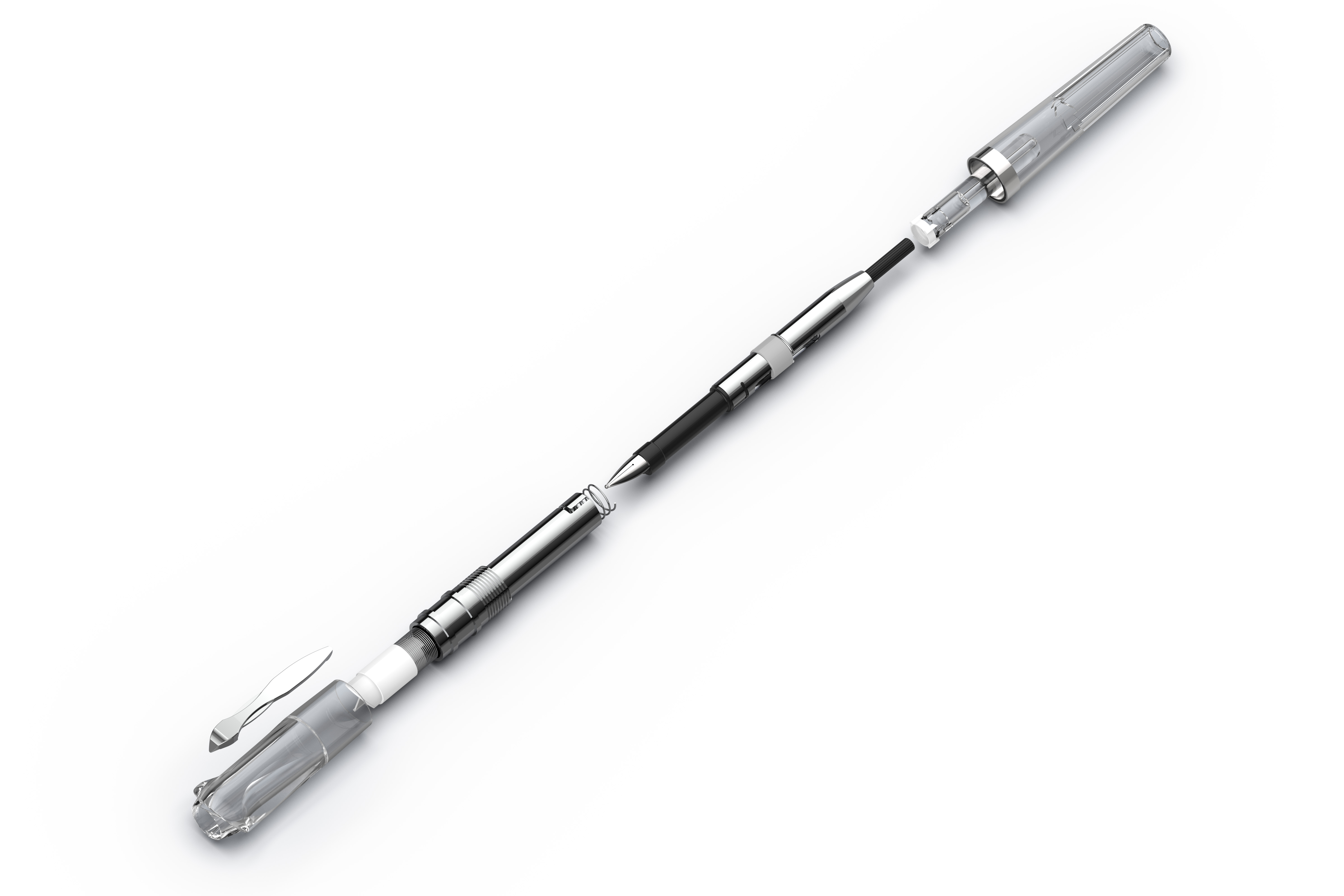
A cross-section of the resolved design, working out the nib-retracting mechanism and how every component seats inside the slim body.

The final Pentel Nomics family — matte black, transparent demonstrator, and iridescent finish.
The transparent demonstrator revealing the internal retracting mechanism.
The demonstrator lit from within, showing the light path through the body.
The progression of grip-refinement prototypes that led to the final Omega form.
Next Project → Pressur
Project 04 / 05

Pressur

Industrial Design · Design for Manufacturing
Inflation, reinvented for the road

A redesign of the external enclosure for a portable tire inflator — keeping all the same internal components while adding new functionality and designing for injection molding and assembly. The key move: a mount that attaches the inflator directly under a bike saddle, with rider-visibility features built into the form.

Design Brief
  • Redesign the enclosure using the same internal components
  • Design must be injection moldable
  • Can be mounted on a bike
  • Add more visibility for the rider
Step 01

Carrying Over the Internals

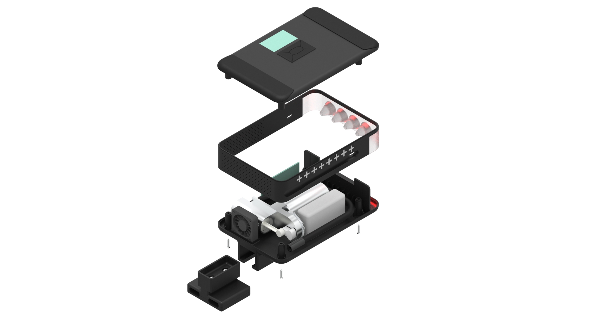
The motor, battery, pump, fan and pipe were carried over unchanged from the original product — the new shell had to package all of them while staying fully injection moldable.

Step 02

Designed for Assembly

An exploded view of the resolved design: a two-part molded shell closes over the internals and PCB, located by screw bosses and locating ribs, with the LED board seated at the rear.

Step 03

Visibility, Every Angle

Reflective tape runs along both sides while four red LEDs sit at the rear — so the rider stays visible from behind and from the side. Vent holes for the fan double as a texture motif.

Step 04

Mounted in Context

The clamp grips the saddle rails directly, tucking the inflator neatly beneath the seat where it stays out of the way until needed.

The final Pressur mounted under the saddle, rear LEDs lit for visibility on the road.
Three views of the finished enclosure — rear lights, side reflective tape, and the clip mount.
Exploded view showing the injection-moldable shell closing over the carried-over internals.
The internal layout: motor, battery, pump, fan and control PCB packaged into the new form.
Next Project → Eventide Ambient Light
← All Work Eventide Ambient Light Hire Me
Project 05 / 05

Eventide Ambient Light

Product Design · 3D Printing · Electronics
Glow, contained

An ambient light enclosure designed entirely around snap-fit assembly — no screws, no glue. It houses an Adafruit Circuit Playground, a lithium-ion battery, and a custom light pipe that channels the board’s NeoPixel LEDs into a soft ambient glow. Every decision was driven by the constraints of 3D printing and clean snap-fit geometry.

Design Brief
  • Assembled entirely with snap-fits — no screws or glue
  • House an Adafruit Circuit Playground, battery and light pipe
  • Light pipe must channel the NeoPixel output
  • Designed around 3D-printing constraints
Step 01

Form Development

The housing took the silhouette of a starship — a wide saucer over a tapered body with two raised nacelles, each a natural vessel for a light element.

Step 02

Snap-Fit Assembly

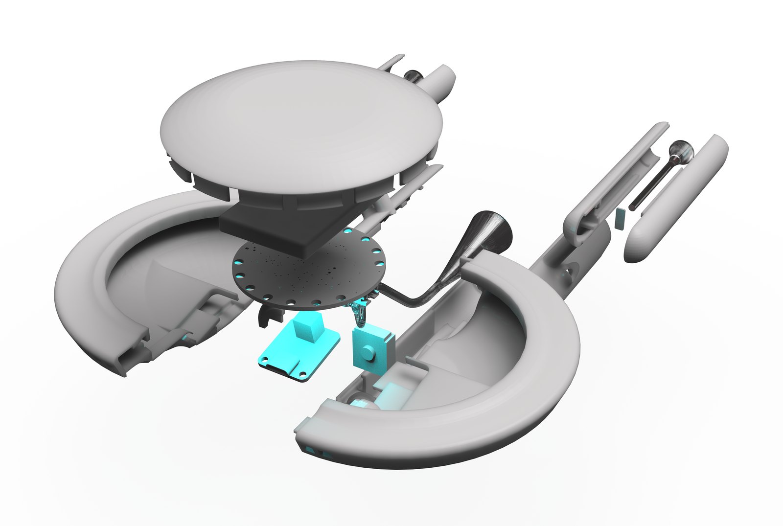
An exploded view of the resolved design: the Circuit Playground, battery and light pipe all locate into the lower body and are captured by the top shell’s snap features — no fasteners anywhere.

Step 03

Seating the Circuit Playground

Looking straight into the saucer: the Adafruit board drops onto its standoffs with the ring of NeoPixels facing out, and the perimeter snap tabs lock the cover down over it.

Step 04

Channeling the Light

A cutaway through the assembled body shows how the light pipe picks up the NeoPixel ring at the saucer and carries it down through the nacelles — the whole optical path resolved inside the snap-fit shell.

Step 05

Tuning the Light

With the electronics seated, the NeoPixels drive the nacelles red and the central core blue — the light pipe carrying each color cleanly to its surface.

The finished Eventide ambient light, nacelles glowing red against a cyan saucer.
The light staged on its halo platform — the signature ambient glow.
Head-on: red nacelles and a blue core, every channel lit by a single Circuit Playground.
The piece at rest within its ring, ambient and sculptural.
Section through the lower body and nacelle, showing the internal structure and snap detail.
Top-down into the saucer: the three light-pipe legs splay out from the central core to feed each channel.
Next Project → 32×32